
#Stm 32 nucleo code#
It will become more clear when you see the example code at the end of this tutorial. So it will be defined inside the setup function. A pinMode function is used for the declaration of digital pins. In Arduino IDE, the setup function is used for declaration or initialization. delay(1000) // waits for one secondĭelay(2000) // waits for two second setup() If you want to add a delay of one second between turning on and turning off an LED, you will use delay(1000). This function is used to generate delays in milliseconds. digitalWrite(PD_2, HIGH) // sets the PD_2 pin as digital highĭigitalWrite(PD_2, LOW) // sets the PD_2 pin as digital low delay(value) For example, if you write digitalWrite(PD_2, HIGH), it will make pin number PD_2 logic HIGH or 3.3 volts and if you write digitalWrite(PD_2, LOW), it will make digital output pin PD_2 LOW or you will get zero volts at the output pin. A first argument is a pin number and the second value to this function is logic state either ‘HIGH’ or ‘LOW’. This function sets or clears digital output pins if the pin has been configured as a digital output pin with pinMode() function. PinMode(PA_5, INPUT) // configure PA_5 pin as a digital output pin digitalWrite(pin_number, value) PinMode(PA_7, OUTPUT) // configure PA_7 pin as a digital output pin pinMode(PD_2, OUTPUT) // configure PD_2 pin as a digital output pin For example, if we write pinMode(22, OUTPUT), it will declare pin number 22 as a digital output pin. The second argument is either INPUT or OUTPUT.

The first argument to this function is a pin number or pin name to which you want to declare either as an input or output. This function is used to configure GIPO pins mode either as an input or output. If you have already used Arduino IDE for Arduino, ESP32, or ESP8266 programming, you will be already familiar with these functions : pinMode(pin_name, pin_mode) These routines are used to configure GPIO pins. To write LED blinking code for STM32 Nucleo, first, we need to understand three main functions available in Arduino IDE. Program STM32 Nucleo GPIO pins with Arduino IDE Note: On Nucleo-64 boards, PA_2 and PA_3 pins are not available per default as they are used by the STLink Virtual Comm Port. We can configure any one of these pins either as a digital input or digital output.
#Stm 32 nucleo how to#
But, we will discuss it in the next tutorial on how to use a push button with STM32 Nucleo and configure GPIO pins as digital input pins. Although these GPIO pins can also be used as digital input pins.

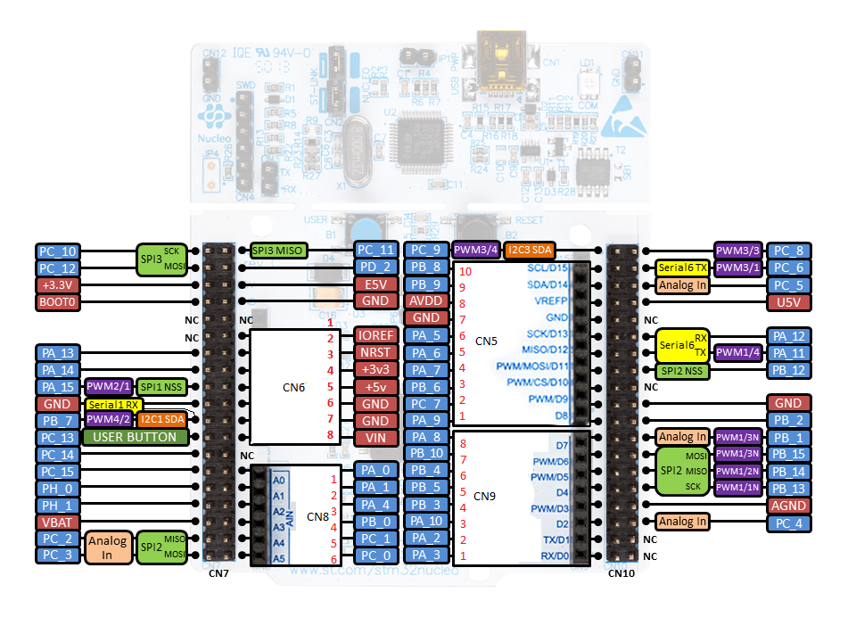
Use STM32 Nucleo GPIO Pins with Arduino IDEĪs mentioned earlier, in this Nucleo tutorial, we will learn how to configure general-purpose input-output pins of STM32 Nucleo as digital output pins. The following diagrams of different connectors of Nucleo-F103RB board show various GPIO pins for UART, I2C, SPI, ADC, CAN, Timers output, and USB communication.įor more information on GPIO pins and to check the pinout of Nucleo-F103RB, you can refer to this link. But you can use only one functionality at a time. We can use any one of these pins as a digital input or digital output.Įach GPIO pin may have multiple functions. Various features of Nucleo-F103RB are mentioned below: Features and PeripheralsĪccording to the above table, this STM32 Nucleo board has 51 general purpose input-output pins. The Nucleo-F103RB board comes with an STM32F103RBT6 microcontroller which is ARM®32-bit Cortex®-M3 CPU. But you can use any other Nucleo board also and follow the same instructions to use GPIO pins as digital output pins. But the one which we are going to use in this tutorial is a Nucleo-F103RB board. Getting Started with STM32 Nucleo in Arduino IDE STM32 Nucleo GPIO PinsĪs discussed in the previous tutorial, there are many variants of STM32 Nucleo boards are available.


 0 kommentar(er)
